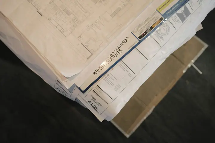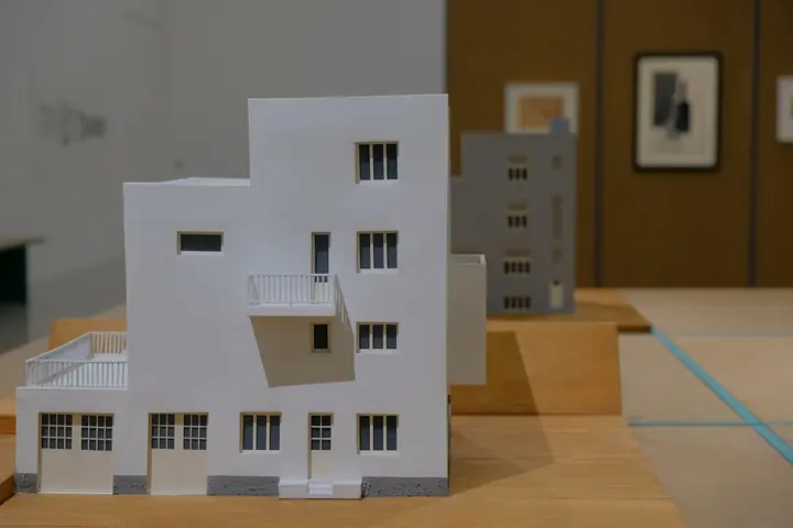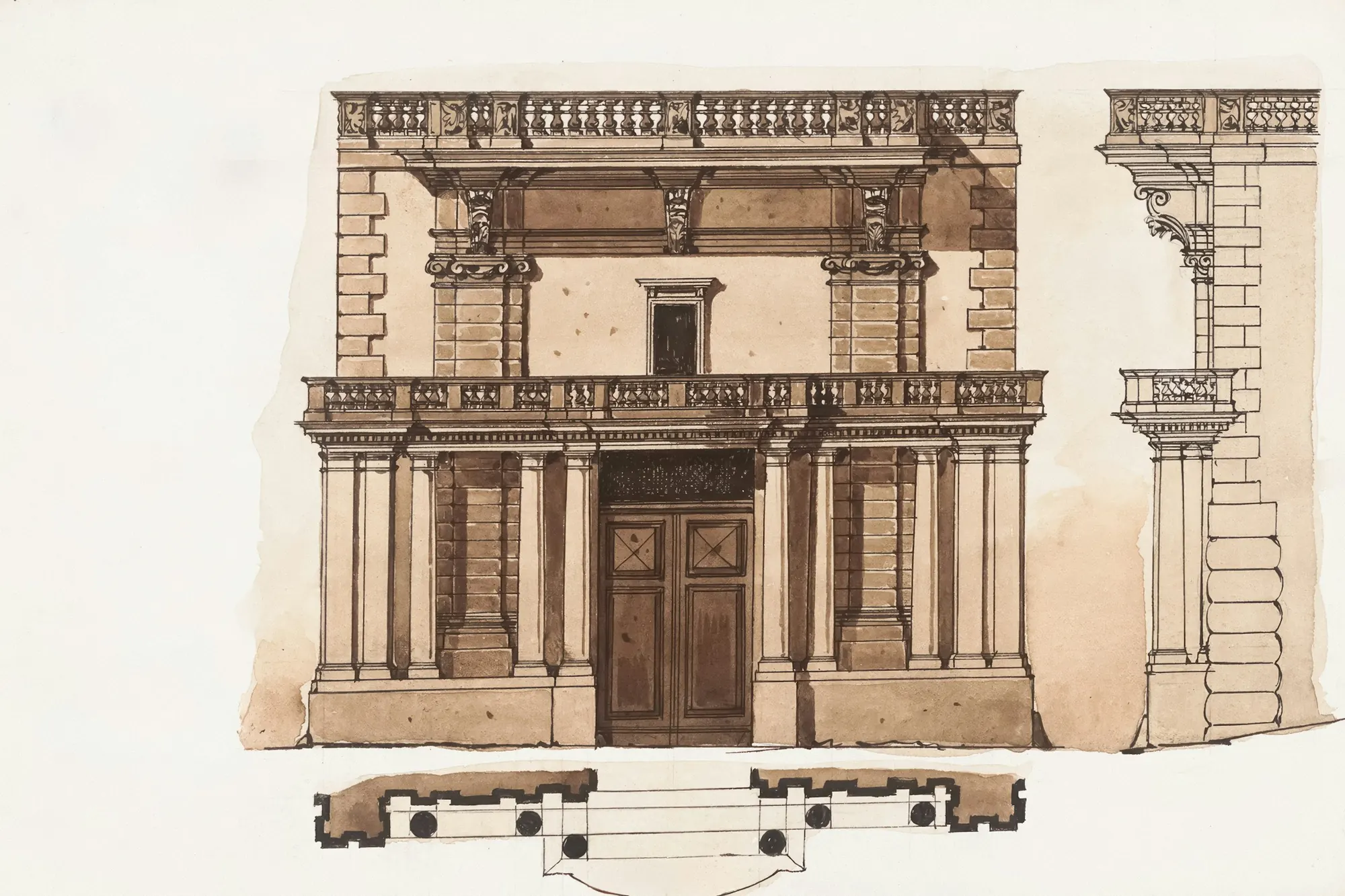
An architectural elevation tells the team what a building should look like. Shop drawings explain how that elevation becomes aluminium members, glass, seals, brackets and joints. They are the bridge between design and fabrication. Reviewing them is more than checking whether the grid looks right: a drawing can match the appearance and still miss a drainage path, a movement allowance or a buildable connection. This guide gives architects, consultants and project managers a practical order for reading a facade submission before it is released to the factory.
Confirm the basis of the submission
Start with the drawing register, project specification and approved architectural issue. Check the title block, date, scale, revision, status and the area covered. Is the sheet for review, for construction or superseded? Are the building grids and levels the same as the structural and architectural drawings? If an area is still awaiting a site survey, the sheet should say so. A dimension copied from an early tender set should not silently become a cutting dimension. Mark the assumptions that need confirmation before fabrication.
Read the submission as a set rather than as isolated attractive elevations. General arrangements show where each system sits; plans and sections show depth and interface; details show assembly; schedules define glass, panels, hardware and finishes. Calculations, material data and test proposals support the drawings. If a detail is labelled 'typical', ask where it stops being typical. Corners, steps in slab edge, roof junctions and entrance bays often need their own sections because their geometry and water paths differ.
Trace one bay from outside to inside
Pick a representative bay and follow every layer. Locate the glass or cladding, pressure plate or structural seal, frame, thermal break if specified, internal air seal, insulation and backing wall. Check that the assembly has somewhere to accommodate tolerance and movement. At the sill, ask where incidental water collects and where it exits; at the head, ask how water from the construction above is kept out. A dimensioned section is more useful than a note saying 'seal all around' because every seal needs a substrate, access and a reason.
Next trace the bay's load path. Glass and aluminium transfer wind loads through mullions, transoms and brackets to the building structure. The drawing should identify the bracket type, substrate, fixing arrangement and any slotted movement connection. Compare it with the engineer's calculations and structural edge condition. A bracket drawn into an empty zone or a congested slab edge is a coordination problem, not a detail that site workers should solve by eye.
Read schedules against the elevations
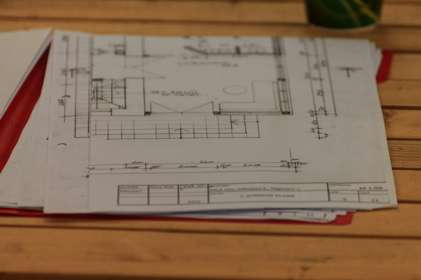
Every glass or panel type needs an unambiguous mark. Cross-check several marks on the elevations against the schedule: make-up, thickness, coating orientation where relevant, safety treatment, colour and performance requirements. Confirm that the schedule distinguishes vision glass, spandrel glass, doors, overhead glass and balustrades where their duties differ. A generic note such as 'toughened glass as required' leaves too much unresolved for procurement. The final selection should follow the approved specification and the facade consultant's review.
For opening windows and doors, check handing, clear opening, restrictors, locks, thresholds and how the units can be maintained. A handle shown on the wrong side may seem minor until the adjacent wall or railing blocks it. For cladding, check panel dimensions, joint width, support rails, access to fixings and the insulation and cavity barrier details provided by the wider design team. An item absent from a schedule can easily become an exclusion in the contract or a delay on site.
Look hardest at interfaces
Most facade problems are not in the middle of a standard panel. They occur where curtain wall meets masonry, a balcony slab, a parapet, a door threshold, a different facade system or a roof. Follow the air seal and water line continuously across those junctions. Check who supplies each flashing, membrane, fire-stopping element and sealant, and who installs it. The facade drawing should not imply that another trade has designed an interface when neither package contains it.
Check the movement assumptions. A building frame deflects; aluminium expands and contracts; construction tolerances vary. The shop drawings should identify fixed and sliding points, joint gaps and the survey dimensions used. A visually perfect zero-gap detail can be impossible to install or can buckle once temperature changes. Ask the designer to explain any movement joint or bracket that is hard to understand. The explanation should be reflected on the approved sheet, not left only in an email.
Close comments before fabrication
Use a comment register that names the sheet, detail and required response. Distinguish a design decision from a drafting correction and from information that can be verified on site. When a revised drawing arrives, confirm that linked sheets and schedules changed too. Record approval conditions clearly. Only the agreed issue should be released for ordering glass and cutting profiles; later changes can be expensive because components may already exist. Keep a clean audit trail of who reviewed what and when.
The aim of review is a coordinated, buildable envelope, not a pile of stamps. A strong submission lets an installer find a location, identify its components and understand how it attaches, seals, drains and moves. It also lets the owner maintain the facade years later. If the drawing cannot answer those questions, request the missing information while change is still easy.
Ask what the drawing does not show
A useful final review is to imagine an installer standing at the opening with only this approved set. Can they tell which bracket belongs there, which edge is fixed, how the unit is lifted and where the weather seal is made? Can the surveyor identify the datum? Can procurement match every glass and coating mark to a schedule? If the answer depends on a phone call to the designer, add the missing note or detail. Ambiguity in the factory or on a scaffold becomes a variation, a delay or an improvised connection.
Read dimensions in both directions and across sheets. An elevation width should agree with the plan opening, a section depth with the bracket projection, and a schedule mark with the glass shown in that bay. Check that the title block makes the intended scale clear; never measure a critical dimension from a printed drawing. Where a structural drawing shows a beam or slab edge different from the architecture, raise a coordinated query rather than silently choosing one. The shop set should document the resolved geometry.
Finally, keep the review proportionate. A standard repeated bay may need one fully developed detail plus a clear map of where it applies. A unique corner or large entrance should not be hidden behind that standard detail. Prioritise questions that affect safety, water, movement, appearance or future replacement. The best approval is one that lets the next team build the design consistently and lets the owner understand what was installed after the project team has left.
General guidance for orientation, not a specification. Applicable standards, values and details are confirmed per project with the facade consultant.